عضویت
عضویت  ورود اعضا
 راهنمای خرید


FX3S Brochure0 pages

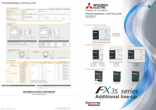
PROGRAMMABLE CONTROLLERS
50/60 Hz
Operation can be continued upon occurrence of
instantaneous power failure for 10 ms or less.
250 V 1 A
15 A max. 5 ms or less/100 V AC, 28 A max. 5 ms
or less/200 V AC
Power consumption*1 19 W
19 W
20 W
21 W
24 V DC service power 400 mA
supply
Function and
performance
High-end Model
*1 : This item shows values when all 24 V DC service power supplies are used in
the maximum configuration connectable to the main unit, and includes the
input current (5 or 7 mA per point).
Superior speed, power, and flexibility.
Realize high speed control, network support,
data logging, and more.
■24 V DC Input (sink/source) specifications
(Please see the manual for input circuit configuration.)
Item
Number of input points
Input connecting type
Input form
Input signal voltage
Input
X000 to
impedance
X007
X010 to
X017
Input signal X000 to
current
X007
X010 to
X017
ON input
X000 to
sensitivity
X007
current
X010 to
X017
OFF input sensitivity
current
Input response time
Input signal Sink input
form
Source
input
Input circuit insulation
Input operation display
Standard Model
From automation to network, to more advanced control.
Supports features required for basic control and a variety
of applications.
Entry level Model
NEW
Function and performance
FX3 series is the 3rd generation of
micro programmable controllers.
Extension
Extension
High speed, large capacity, and enhanced performance and
10
functions are assured.
30
Extension
Remote I/O*
30
60
Equipped with excellent expandability for analog, communication,
Ethernet, and positioning functions, a whole world of FX applications
awaits.
Extension
Remote I/O*
256
7 mA/24 V DC
—
5 mA/24 V DC
4.5 mA or more
—
3.5 mA or more
1.5 mA or less
Approx. 10 ms
No-voltage contact input
NPN open collector transistor
No-voltage contact input
PNP open collector transistor
Photocoupler insulation
LED on panel lights when photocoupler is driven.
Relay output specification
FX3S FX3S FX3S FX3S 10MR/ES 14MR/ES 20MR/ES 30MR/ES
Number of output points 4 points
6 points
8 points
14 points
Output connecting type Fixed terminal block (M3 screw)
Output form
Relay
External power supply 30 V DC or less, 240 V AC or less (250 V AC or
less when the unit does not comply with CE, UL or
cUL standards.)
Max. load Resistance 2 A/point
The total load current of resistance loads per
load
common terminal should be the following value.
• 1 output point/common terminal: 2 A or less
• 4 output points/common terminal: 8 A or less
Inductive
80 VA (UL and cUL standards approved at 120 and
load
240 V AC.)
Min. load
5 V DC, 2 mA (reference value)
Open circuit leakage current —
Response OFF→ON
Approx. 10 ms
time
ON→OFF
Output circuit insulation Mechanical insulation
Output operation display LED on panel lights when power is applied to relay coil.
384
■Transistor output specifications
(Please see the manual for output circuit configuration.)
128
Item
Number of output points
Output connecting type
Output form
256
384
Number of control points
External power supply
Max. load Resistance
load
Inductive
load
NEW
Main unit I/O
Control size
10/14/20/30 points
Max. 30 points
14/24/40/60 points
Max. 128 points
(Max. 256 with remote I/O*)
16/32/48/64/80/128 points
Max. 256 points
(Max. 384 with remote I/O*)
Power supply
AC
AC, DC
AC, DC
24 V DC input
Sink/Source
Sink/Source
Relay Type
Transistor Type
Relay Type
Transistor Type
Relay Type
Transistor Type
Internal memory
16,000 steps EEPROM
(program capacity is
limited to 4,000 steps.)
32,000 steps EEPROM
64,000 steps RAM
(Battery backed)
Communication port
USB/RS-422
USB/RS-422
High-speed counter
1-phase
60 kHz : 4 points
10 kHz : 2 points
1-phase
100 kHz : 6 points
10 kHz : 2 points
Positioning
control
(transistor output
type)
2 axes
100 kHz
14/24 Point type : 2 axes
40/60 Point type : 3 axes
100 kHz
2 points
2 points
□□
□□
□□
□□
FX3S-CNV-ADP
2-φ4.5 mounting holes
W1
75 (2.96'')
(Mounting hole pitches)
W
PROGRAMMABLE CONTROLLERS
14.6
(0.58˝)
74 (2.92˝)
MASS (Weight): 0.1 kg (0.22 lbs)
Unit: mm (inches)
Accessoriest:t Dust proof protection sheet
tt Manual supplied with product
Installationt :t 35 mm (1.38") wide DIN rail or Direct installation (with M4 screws)
Series
W: mm (inches)
W1: mm (inches)
Direct mounting hole pitches
MASS (Weight):
kg (lbs)
FX3S -10M
60(2.37")
52(2.05")
0.30(0.66 lbs)
FX3S -14M
60(2.37")
52(2.05")
0.30(0.66 lbs)
FX3S -20M
75(2.96")
67(2.64")
0.40(0.88 lbs)
FX3S -30M
100(3.94")
92(3.63")
0.45(0.99 lbs)
■Product specification
Series
Main Units
Power
Supply
Model name
FX3S -10MR/ES
FX3S -10MT/ES
100 to
240 V AC
Input Specifications
Output Specifications
Number of
Number of
Input type
points
points
6
6
24 V DC
(Sink/
Source)
Output type
4
Relay
NEW
4
Transistor
(Sink)
NEW
FX3S -10MT/ESS
6
4
Transistor
(Source)
NEW
FX3S -14MR/ES
8
6
Relay
NEW
FX3S -14MT/ES
8
6
Transistor
(Sink)
NEW
FX3S -14MT/ESS
8
6
Transistor
(Source)
NEW
FX3S -20MR/ES
12
8
Relay
NEW
FX3S -20MT/ES
12
8
Transistor
(Sink)
NEW
FX3S -20MT/ESS
12
8
Transistor
(Source)
NEW
FX3S -30MR/ES
16
14
Relay
NEW
FX3S -30MT/ES
16
14
Transistor
(Sink)
NEW
FX3S -30MT/ESS
16
14
Transistor
(Source)
NEW
Connector
conversion
adapter
FX3S -CNV-ADP
Special adapter connection conversion adapter
Special
adapters
FX3U -232ADP-MB
For RS-232C(MODBUS)communication
FX3U -485ADP-MB
For RS-485(MODBUS)communication
FX3U -ENET-ADP*4
4-ch voltage/current input
FX3U -4DA-ADP
4-ch voltage/current output
FX3U -3A-ADP
NEW
For Ethernet communication
FX3U -4AD-ADP
2-ch voltage/current input
1-ch voltage/current output
FX3U -4AD-PT-ADP 4-ch platinum resistance thermometer sensor input (-50 to +250 ℃)
FX3U -4AD-PTW-ADP 4-ch platinum resistance thermometer sensor input (-100 to +600 ℃)
FX3U -4AD-PNK-ADP 4-ch Pt1000/Ni1000 resistance thermometer sensor input
FX3U -4AD-TC-ADP 4-ch thermocouple (K, J type) temperature sensor input
Expansion
boards
For RS-232C communication
FX3G -422-BD
For RS-422 communication
FX3G -485-BD
For RS-485 communication
FX3G -8AV-BD
For 8-ch Analog volume
FX3G -2AD-BD
2-ch voltage/current input
FX3G -1DA-BD
Memory
cassette
FX3G -232-BD
1-ch voltage/current output
FX3G -EEPROM-32L 32,000 steps EEPROM memory (with transfer switch)*5
New possibilities
*4 : FX3U -ENET-ADP Ver. 1.20 or later is applicable to the FX3S series PLC.
*5 : FX3S series PLC can hold 16,000 steps of memory, but user program capacity is limited to 4000 steps.
− Introducing an entry level model for the FX3 series −
3 axes
100 kHz
Variable analog
potentiometer
Performance
Stored program repetitive operation system with
interruption function.
Input/output control system
Batch processing system (when END instruction is
executed)
Input/output refresh instruction and pulse catch function
are provided.
Programming language
Relay symbol system + step-ladder system (SFC
notation possible)
Program Built-in memory capacity/ 16,000 steps/EEPROM memory (Program capacity is
4000 steps.)
memory type
Max. allowable write: 20,000 times
Memory cassette
32,000 steps/EEPROM memory (with loader function)
(Option)
The FX3S series PLC is available only to 16,000 steps.
(Program capacity is 4000 steps.)
Max. allowable write: 10,000 times
Writing function during Provided (Program can be modified while the PLC is
running
running.)
Keyword function
With keyword/Customer keyword function
Real-time Clock function*2
Built-in
1980 to 2079 (with correction for leap year)
clock
2- or 4-digit year, accuracy within 45 seconds/month at
25 ℃
Kinds of
Basic instructions
Sequence instructions: 29
Step-ladder instructions: 2
instructions
Applied instructions
116 kinds
Processing Basic instructions
0.21 μs/instruction
speed
Applied instructions
0.5 μs to several hundred μs/instruction
Number of Input points
16 points or less (Extension is impossible.)
input/output Output points
14 points or less (Extension is impossible.)
points
Input/output Input relay
X000 to X017
The device numbers are octal.
relay
Output relay
Y000 to Y015
Auxiliary For general
M0 to M383
384 points
relay
EEPROM keep
M384 to M511
128 points
For general
M512 to M1535
1024 points
For special
M8000 to M8511 512 points
State
For initial state
S0 to S9
10 points
(EEPROM keep)
EEPROM keep
S10 to S127
118 points
For general
S128 to S255
128 points
Timer
100 ms
T0 to T31
32 points 0.1 to 3,276.7 sec
(on-delay 100 ms/10 ms
T32 to T62
31 points 0.1 to 3,276.7 sec/0.01 to
timer)
327.67 sec
When M8028 is driven ON,
timers T32 to
T62 (31 points) are
changed to 10 ms
resolution.
65 points 0.001 to 32.767 sec
1 ms
T63 to T127
1 ms accumulating type T128 to T131
4 points 0.001 to 32.767 sec
100 ms accumulating type T132 to T137
6 points 0.1 to 3,276.7 sec
Variable analog potentiometers
Available as analog timers
VR1: D8030 VR2: D8031
C0 to C15
16 points Counting from 0 to 32,767
Counter 16 bits up (For general)
16 bits up (EEPROM keep) C16 to C31
16 points Counting from 0 to 32,767
32 bits up/down (For
C200 to C234
35 points Counting from
general)
-2,147,483,648 to
+2,147,483,647
High1-phase 1-count input in C235 to C245
Counting from -2,147,483,648 to
both directions (32 bits
+2,147,483,647
speed
up/down)
counter
(EEPROM keep)
1-phase 2-count input in C246 to C250
both directions (32 bits
up/down)
(EEPROM keep)
2-phase 2-count input in C251 to C255
both directions (32 bits
up/down)
(EEPROM keep)
For general (16 bits)
D0 to D127
128 points
Data
register For EEPROM keep (16 bits) D128 to D255
128 points
(32 bits
For general (16 bits)
D256 to D2999
2744 points
when
File register
D1000 to D2999 Max.
Can be set as file registers
paired)
(EEPROM keep)
2000
in units of
points 500 points from D1000 in
the program
area (EEPROM) using
parameters.
D8000 to D8511 512 points
For special (16 bits)
For index (16 bits)
V0 to V7
16 points
Z0 to Z7
Pointer
For branching of JUMP P0 to P255
256
For CJ instructions and
and CALL
points CALL instructions
6 points
Input interruption
I0 to I5
Timer interruption
I6 to I8
3 points
Nesting For master control
N0 to N7
8 points For MC instructions
Constant Decimal number (K)
16 bits
-32,768 to +32,767
32 bits
-2,147,483,648 to +2,147,483,647
Hexadecimal number (H) 16 bits
0 to FFFF
32 bits
0 to FFFFFFFF
Real number (E)
32 bits
-1.0 x 2128 to -1.0 x 2-126 , 0 ,
1.0 x 2-126 to 1.0 x 2128
Decimal-point and exponential
notations are possible.
Software/peripheral equipment
GX Works2
Version 1.492N or later *3
Version 1.50 or later
FX-30P
RS-422 (USB option)
1-phase
60 kHz : 2 points
10 kHz : 4 points
Transistor output specification
FX3S FX3S FX3S FX3S 10MT□
14MT□
20MT□
30MT□
4 points
6 points
8 points
14 points
Fixed terminal block (M3 screw)
Transistor/sink output (FX3S -□MT/ES)
Transistor/source output (FX3S -□MT/ESS)
5 to 30 V DC
0.5 A/point
The total load current of resistance loads per
common terminal should be the following value.
• 1 output point/common terminal: 0.5 A or less
• 4 output points/common terminal: 0.8 A or less
12 W/24 V DC
The total of inductive loads per common terminal
should be the following value.
• 1 output point/common terminal: 12 W or less/
24 V DC
• 4 output points/common terminal: 19.2 W or
less/24 V DC
0.1 mA or less/30 V DC
1.5 V or less
Y000, Y001: 5 μs or less/10 mA or more (5 to 24 V DC)
Y002 to Y015: 0.2 ms or less/200 mA or more (at 24 V DC)
Photocoupler insulation
LED on panel lights when photocoupler is driven.
FX3S
Item
Operation control system
Sink/Source
Output
Hardware
4.3 kΩ
Item
Number of control points
Built-in features
—
FX3S 30M□
16 points
■Relay output specifications
(Please see the manual for output circuit configuration.)
Simple and cost effective. Basic model that supports
analog and communication expansion.
Perfect for simple automation tasks.
FX3 series feature
comparison
Specification
FX3S FX3S FX3S 10M□
14M□
20M□
6 points
8 points
12 points
Fixed terminal block (M3 screw)
Sink/Source
24 V DC +10%, -10%
3.3 kΩ
■External Dimensions
90 (3.55'')
Supply voltage
Allowable supply
voltage range
Rated frequency
Allowable instantaneous
power failure time
Power fuse
Rush current
FX3S 30M□/E□
■Performance specifications
(General specification is the same as that of FX3U series.
Please see the "MELSEC FX-FAMILY" catalog.)
90 (3.55'')
All-inclusive
Item
Specification
FX3S FX3S FX3S 10M□/E□
14M□/E□
20M□/E□
100 to 240 V AC
85 to 264 V AC
82 (3.23'') (Mounting hole pitches)
■Power Supply Specifications
—
Open circuit leakage current
ON voltage
Response OFF→ON
time
ON→OFF
Output circuit insulation
Output operation display
*2 : The current time of the clock is backed up by the capacitor built-in the PLC. Supply
the power to the PLC for 30 minutes or more to completely charge this large-capacity
capacitor.
(The capacitor works for 10 days [atmosphere: 25 °C])
*3 : To program FX3S in GX Developer, select FX3G as the PLC type. Please read the FX3S
series user's manual about limitations.
Safety Warning
Registration
To ensure proper use of the products in this document, please be sure to read the instruction manual prior to use.
••Ethernet is a trademark of Xerox Corporation in the United States.
••MODBUS is a registered trademark of Schneider Electric SA.
••All other company names and product names used in this document are trademarks or registered trademarks of their
respective companies.
HEAD OFFICE: TOKYO BLDG., 2-7-3, MARUNOUCHI, CHIYODA-KU, TOKYO 100-8310, JAPAN
http://Global.MitsubishiElectric.com
* : Remote I/O is CC-Link I/O.
HIME-L063-A1305(MEE) Printed in Japan
New publication, effective May 2013
Specifications subject to change without notice.
NEW
"