عضویت
عضویت  ورود اعضا
 راهنمای خرید


LongRT Base Unit0 pages
Engineering SpecSheet
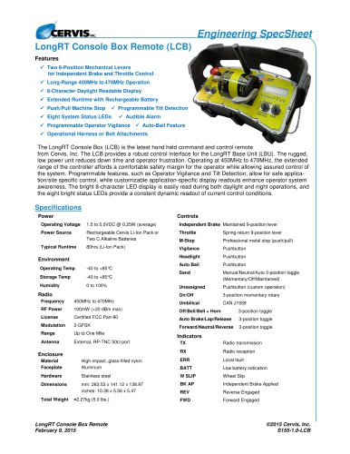
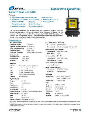
LongRT Base Unit (LBU)
Features
Rugged High-Impact Polymer Enclosure
Real-Time Clock
8-Character LED Display CAN Capable
16-Digital I/O, 2-AO, 2-AI
450MHz to 470MHz
Logging
Field Upgradeable
Removable Antenna
2-Form-C Relays
Weatherproof Design
2-Frequency Counters
WSLO-5544
The LongRT Base Unit (LBU) represents the next generation of Cervis configurable command and control machine-mounted units. Designed for safety, the LBU
employs a dual processor architecture compliant with ISO 13849 Category 3 Pld.
Versatile and configurable, the LBU enables complex command and control solutions in harsh environments and industrial applications.
Specifications
Max. Power Ratings
Operating Voltage
Form-C RELAY (Two, M17 & M18)
7 to 30VDC
Reverse Voltage Protection Up to -40VDC
Over Voltage Protection
Up to 60VDC
Operating Power
1W @ 12VDC
Max. Cont. I Sourcing
15A @ +55°C (all channels)
Environment
Operating Temp
Storage Temp
Humidity
-40 to +85°C
-40 to +85°C
0 to 100%
Max. Contact V
277VAC, 30VDC
Max. Contact I
8A max. switching @ 250VAC or VDC
Analog Output (Two, M19 & M20)
Voltage Range
0V to Input Voltage
Drive Current
30mA
Analog Input (Four, M21–M24)
Voltage Range
0V to Input Voltage
Input Impedance
10000
Analog Input (Two, M25 & M26)
Indicators
L1–L4
Available for application specific use
TX
Lit when message transmitted
RX
Lit when message received
LNK
Lit when safety-link is active
HB
Blinks during normal operation
Display
8-character LED
Frequency Counters
Serial Communications
CAN Protocol
SAE J1939/CANopen
RS-232 Port
Upgrade/Debug
Enclosure
Dimensions
cm: 21.59 x 16.31 x 5.715
inches: 8.75 x 6.42 x 2.25
Total Weight
0.680kg (1.5lbs)
Digital I/O (16)
Outputs
M1–M16
Type
High-Side switch
Max. Source I
4A
Frequency
450MHz to 470MHz
Avg. Source I
2A
RF Power
100mW (+20 dBm max)
One H-Bridge
M1 & M2
License
Certified FCC Part-90
Output Protection
Over current; under current; over temp.
Modulation
2-GFSK
PWM Frequency
0 – 1000Hz*
Range
Up to One Mile
M1–M16
Current sense
Antenna
External, RP-TNC 50 port
INPUT
Type
I Sense Threshold
Radio
5mA typical; 10mA max.
*1000Hz max. when a single channel is configured for PWM output. Increasing the number of PWM channels decreases the max. PWM
frequency.
** For best performance, do not connect antenna directly to the base unit. Instead, Cervis recommends to use an extension cable with an
antenna base plate mount.
LongRT Base Unit
February 9, 2015
©2015 Cervis, Inc.
S154.1.0-LBU