عضویت
عضویت  ورود اعضا
 راهنمای خرید


Model 556B Acquisition Interface Module0 pages
Features
t PHA acquisition server with
Ethernet interface
Model 556B
Acquisition Interface Module
■
t Two ADC inputs per module
■
t High speed acquisition – up to
1 MHz data acceptance rate
■
t 64K, 32-bit channels of local
acquisition memory
■
t PHA and Loss-Free PHA
acquisition modes
■
t Fast spectral data transfers
using Ethernet
■
t Host interface for controlling
the programmable
ICB NIM Family
■
t Live spectral displays
and complete front end
programmability through any
Genie™ family workstation
■
Description
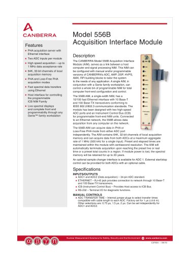
The CANBERRA Model 556B Acquisition Interface
Module (AIM), serves as a link between a host
computer and signal processing NIM. This NIM can
be configured with manual and/or programmable
versions of CANBERRA’s ADC, AMP, DSP, HVPS,
AMX, RPI building blocks to tailor the system
to the needs of any application. A single AIM, in
conjunction with a Genie family workstation, can
control a whole bin of programmable NIM for total
computer front-end configuration and control.
The 556B AIM, a single-width NIM, has a
10/100 fast Ethernet interface with 10 Base-T
and 100 Base-TX transceivers conforming to
IEEE 802.2/802.3 communication standards. The
module has been designed with two high-speed
ADC ports and an Instrument Control Bus (ICB)
for programmable front-end NIM units. Connected
to an Ethernet network, the 556B allows data
acquisition from any computer on the network.
The 556B AIM can acquire data in PHA or
Loss-Free PHA mode from either ADC port
independently. The AIM contains 64K, 32-bit channels of local acquisition
memory and can acquire data from both ADCs at a maximum aggregate
rate of 1 MHz (500 kHz for a single input). Preset and elapsed times are
maintained within the module with centisecond resolution. The AIM will
automatically terminate acquisition upon reaching the preset live or real
time or a preset total counts in a region. If module power is lost, the spectral
memory will be retained for up to 20 years.
An optional sample changer interface is available for ADC 1. External start/stop
control can be provided for both ADCs with an optional cable.
Specifications
INPUTS/OUTPUTS
ADC1 and ADC2 (Data acquisition) – 34-pin ADC standard.
ETHERNET – RJ-45 jack provides connection to network through 10 Base-T
and 100 Base-TX transceivers.
■t ICB (Instrument Control Bus) – Provides Host access to ICB Bus.
■t RS-232 – Terminal I/O for diagnostic functions.
■t
■t
MANUAL CONTROLS
■t
ADC TRANSFER TIME – Internal jumper plugs to select transfer times
compatible with cable length to each ADC. Factory set for 1 µs (≤4.6 m).
Other selections are: 0.75 µs, 1.5 µs, 2 µs. Can be set independently for
ADC1 and ADC2.
Nuclear Measurement Solutions for Safety, Security and the Environment
www.canberra.com
C37924 – 06/10