عضویت
عضویت  ورود اعضا
 راهنمای خرید


VT7EE/VT7EES0 pages

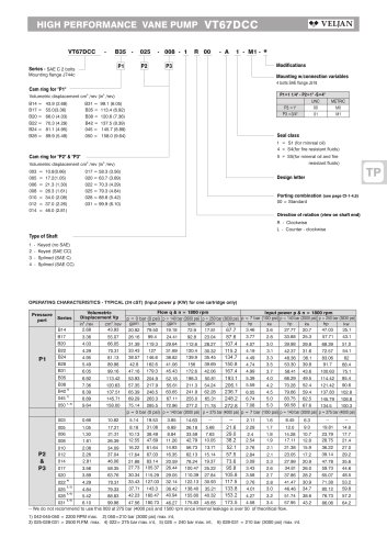
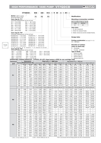
HIGH PERFORMANCE VANE PUMP VT7EE / VT7EES
nnnnVT7EE or VT7EES - 066 - 045 - 1 R 00 - A 1 0 - 00 *
nnnnSeries-
nnnnVT7EE series- 250 B4HW
nnnnISO 3019-2 mounting flange
nnnnVT7EES series- SAE E 4 bolts
nnnnMounting flange J744c
nnnnCam ring for "P1" & "P2"—
nnnnVolumetric displacement cm3/rev (in3/rev)
nnnn042 = 132.2 (8.07) 057 =
nnnn045 = 142.5 (8.70) 062 =
nnnn050 = 158.5 (9.67) 066 =
nnnn052 = 163.8 (10.0) 072 =
nnnn054 = 170.9 (10.43) 085 =
nnnnType of shaft VT7EE -
nnnn2 - keyed G45N(ISO/R775 -G38M)
nnnnType of shaft VT7EES
nnnn1 - keyed (SAE CC)
nnnn3 - splined (SAE CC)
nnnn4 - splined (SAE D & E)
nnnn5 - splined (SAE D & E)
nnnn183.2 (11.18)
nnnn196.6 (12.0)
nnnn213.0 (13.0)
nnnn227.1 (13.86)
nnnn268.7 (16.40)
nnnnP1
nnnnModifications
nnnnMounting W/connection variables
nnnnP1&P2=11" S=4" | ||
VT7EES | VT7EE-VT7EES | |
Type | UNC | METRIC |
code | 00 | M0 |
Coupling adaptor
nnnn0 - none
nnnn2 - SAE B
nnnn3 - SAE BB
nnnnSeal class
nnnn1 - S1 (for mineral oil)
nnnn4 - S4 (for fire resistant fluids)
nnnn5 - S5 (for mineral oil and fire resistant fluids)
nnnnDesign letter
nnnnPorting combination (see page BM-1-5)
nnnn00 - standard
nnnnDirection of rotation
nnnn(view on shaft end)
nnnnR - clockwise
nnnnL - counter-clockwise
nnnnINTERNAL LEAKAGE (TYPICAL)
nnnn(9.0) 34 r
nnnn(8.0) 32
nnnn(7.0)
nnnn(6.0) 24 -
nnnn(5.0)
nnnn(4.0)
nnnn(3.0) 12-
nnnn(2.0)
nnnn(1.0)
nnnn0 -
nnnn0
nnnn---10 cSt - 24 cSt | y y y | |||||
y y y | y | |||||
P1-P2 y y | y y | |||||
y y | ||||||
—y y y y | ||||||
y y y | P1-P2 | |||||
s y | y | |||||
y | y y | |||||
y y ^ y^~~^ | ||||||
NOISE LEVEL (TYPICAL)
nnnnVT7EE- 050-050
nnnn105
nnnn(1500)
nnnn140
nnnn(2000)
nnnn175
nnnn(2500)
nnnn210
nnnn(3000)
nnnnPressure in bar (psi)
nnnnDo not operate pump more than 5 seconds at any speed or
nnnnviscosity if internal leakage is more than 50% of theoretical flow.
nnnnTotal leakage is the sum of each section loss at its operating conditions.
nnnnO
nnnnin
nnnn<
nnnnÖ
nnnn>
nnnnO
nnnn240
nnnn(3500)
nnnnInlet pressure 0.9 bar abs Viscosity 32 cSt - n = 1200 RPM ---n = 1800 RPM | ||||||
Lw = Lp + 8 db (A) | ||||||
105
nnnn(1500)
nnnn140
nnnn(2000)
nnnn175
nnnn(2500)
nnnn210
nnnn(3000)
nnnn240
nnnn(3500)
nnnnPressure in bar (psi)
nnnnDouble pump noise level is given with each section discharging at
nnnnthe pressure noted on the curve.
nnnnHYDROMECHANICAL POWER LOSS (TYPICAL)
nnnnPERMISSIBLE RADIAL LOAD
nnnnQ.
nnnntfl
nnnnIfí
nnnnO
nnnn5
nnnno
nnnnQ.
nnnn- — n = 2200 rpm --n = 1800rpm -n = 1200 rpm | ||||||
24 cSt) | P1-P2 | |||||
P1-P2 | ||||||
0 35 70 105 140 175 210 240
nnnn(500) (1000) (1500) (2000) (2500) (3000) (3500)
nnnnPressure in bar (psi)
nnnnTotal hydromechanical power loss is the sum of each section at its
nnnnoperating conditions
nnnn1000 1400 1800
nnnnSpeed n (rpm)
nnnnMaximum axial load permissible Fa = 2000 N (449 Lbs)
"