عضویت
عضویت  ورود اعضا
 راهنمای خرید

060 pages

M25/M36/M350
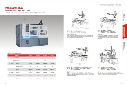
mm&mMmmwmm'p'b: M25, M36, M350
M series-precise linear guideway turning center with 5 axis :M25,M36,M350
*9o&ft*mw, aifflraeff, aMMeaMa.
M series-precise linear guideway turning center with 5 axis is a new high-end model we
just approached, that integrating the compound processing competence like turning,
milling, drilling and tapping so on.
• BODY-With international advanced vertical bed body structure in 90°, and with custom-made excellent resin sand and
die-casting at a whole, strict thermal aging treatment, to make sure the high stiffness."
• SPINDLE- High precision and sleeve-style independent spindle structure, and high speed hydraulic swing system, to
guarantee the high rotating speed."
• High precision linear guideway and ballscrew, with central and pre-stretching ballscrew assembly method, for realizing
the precise turning with tolerance of u level."
• With 90° vertical bed body structure, will bring more processing space, and the chips-removing capability will be better.
• The effective utilization with the 4 axis accurate linkage and compound cutters can realize the turning, milling,drilling and
tapping so on technology processing .
• The fifth axis comfiguration for the vice-spindle or tailstock spindle makes the M-series turning center' function be stronger.
07
Focusing on precise CNC. engaging in industrial robot + smart logistic.
concentrating on smart-factor/ integration
iM^WM: Main parameters
Main parameters | Unit | M25 | M36 | M350 | |
Max.swing diameter | mm | ♦ 480 | ♦ 480 | ♦ 480 | |
Capacity | ft^tHIHHS mm AOIMI Max. turning length """ *Juu | ♦ 300 +300 | |||
g±IZIfl.HS:g mm oon Max.cutting length •3JU | 330 330 | ||||
Max. bar through-hole ^l^oj | 26(35) 40 | ||||
Xtt^sSS mm X-axis travel | 230 | 230 230 | |||
Axis Stroke | Z-axis travel | 330 | 330 330 | ||
YttffaSS mm 420 Y-axis travel | 420 | 420 | |||
W1-axis travel | mm 250 | ||||
W2tt^as (ass) W2-axis travel | mm 310 | 310 310 | |||
Rapid Traverse | X/Z/Y/W1/W25S m/min 20 | 20 20 | |||
Spindle nose size ™" A^~4 | A2-5 A2-5 | ||||
3E» Spindle | Spindle drive motor kva | kW 3.7/5.5 | 3.7/5.5 5.5/7.5 | ||
Spindle speed range | rpm 0-5500 | 0-5000 0-4500 | |||
i$ai#ft^»a , 25®* collet Work piece clamping method (4'iBt/i-£{§ hydraulic chuck) | 36I3S collet , 42ffiJ? collet ( 5'igrf-f=S hydraulic chuck) (6'iSff-f=S hydraulic chuck) | ||||
IUitt«f«StS N/A A2-4 Vice-spindle nose spec ^ | A2-4 A2-4 | ||||
Vice-spindle | Vice-spindle servo motor power o. / r\ vv | O.'IAVV 0.1 F\VV | |||
i!)£$4$fiii5H rDm n-^nnn Vice-Spindle speed range y u suuu | 0-5000 0-5000 | ||||
Vice-Spindle work pieces CR30A4 clamping method | |||||
m,mmm'am. mm 100 Tailstock sleeve stroke | 100 100 | ||||
■a Tailstock | K&9f&W& mm ion Tailstock sleeve diameter ' | ♦ 80 ^80 | |||
SfSS|Sitt?L N/A MT4 Tailstock sleeve borina-hole | MT4 MT4 | ||||
SlRlZI»S! Number of tools in radial | 5 (10) | ||||
7JHS3 | Number of tools in axial | 4 (8) | 4 (8) 4 (8) | ||
Number of power tools in radial J | 3 3 | ||||
Number of power tools in axial | 3 | 3 3 | |||
TIB Toolholder | Toolholder type compound toolholder SlRlilTJIS+'frrS mm 7n Toolholder center height in radial ' u | compound toolholder compound toolholder 70 70 | |||
Tool size 10 10 | 16*16 16*16 | ||||
ifffBS mm w Boring rod diameter C-J | 25 25 | ||||
(HJ§ Accuracy | MS^&ifiifit mm n nno XVZ axis repealing poslioning accuracy U . UUZ | 0.002 0.002 | |||
Cooling motor | 120 120 | ||||
itfJSSJlgS L Rn hydraulic box capacity Du | 60 60 | ||||
fttt Others | , . • kVA ?0 Required electric power ^u | 20 20 | |||
=Ett«1"£>SJft®ft mm ,„,„ Height from floor to spindle center =* 1u 1 u | =1010 =1010 | ||||
tjlfl;/?\t ( ft x 5S X TO ) mm incn*iQcn*iOKn Overall size(L*W*H) 1950 1850 1950 | 1950*1850*1950 1950*1850*1950 | ||||
SUSSES kq -ofinn Net weight J =2600 | = 2700 =2800 | ||||
S»P»ftstandard:ISfB, ttHI$, ffiffl^flfl, ^SPSSE, mmmm, ifflitSSE, SEBSSE, >Sffi«*(-fcS) , MSSJf*,
asffitttoptionai = mmmmnvim, ascites, aa*, earn, ±T»4sst, I^MHA, ean§*4«i,
«*4»s*4«, aatssassi, gajj^ssE, fSj±;#*P^SE
08
"